Advanced Cleanroom Design
Our experienced Design team can support you with all aspects of the design and specification requirements of your project, bringing experience and knowledge of traditional and specialist cleanroom panel systems.
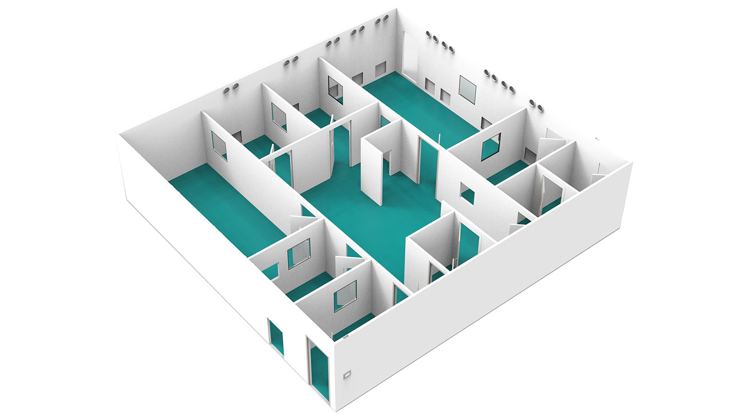
In the detailed design phase, the ideas and concepts evolve into concrete plans, required specifications and exact definitions of dimensions, materials, and components, defined in a User Requirement Specification (URS).
The URS defines processes, equipment, operations, capacities, and environmental criteria for the cleanroom design. Our Design team will review the flow of people and products through the facility to assess the optimum layout for compliance, efficient operation, and minimisation of cross-contamination. Once the URS has been approved, the functional design specification (FDS) will be developed.
We use digital modelling to assess the interrelationship between process, plant and equipment, verifying the accuracy of a technical solution, before we manufacture and install the room.
Every cleanroom, whether it is being retrofit or as part of a complete new build, needs a seamless interface with its surrounding facility.
3D laser surveys enable our design engineers to ensure that the design solution provided is fully optimised to accommodate any existing mechanical and electrical interfaces or existing building layout requirements.
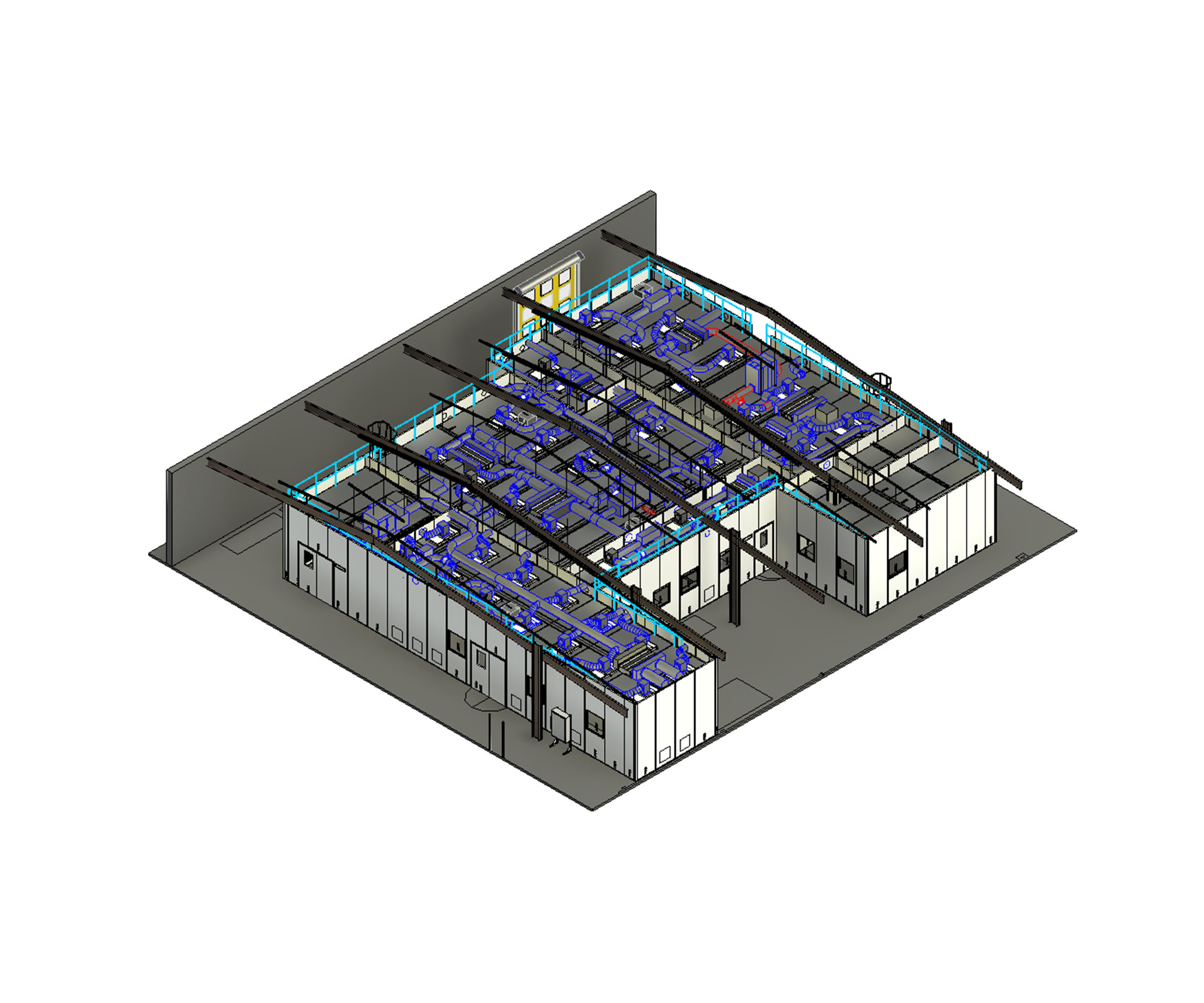
3D building information modelling
3D building information modelling helps optimise a cleanroom design solution.
Our Autodesk-certified design engineers produce designs following the latest BIM standards and workflows, meaning we can collaborate with clients and coordinate with any other contractors involved in a facility build, resulting in greater accuracy and higher quality results.
Using modern surveying equipment, we 3D scan the current environment of our client’s facilities and carry out clash detection to verify that the proposed cleanroom design operates in line with the planned process and its surrounding environment.
2D and 3D models allow you to visualise the project, including virtual reality walk-through tours to test the layout and workflow.
Airflow modelling
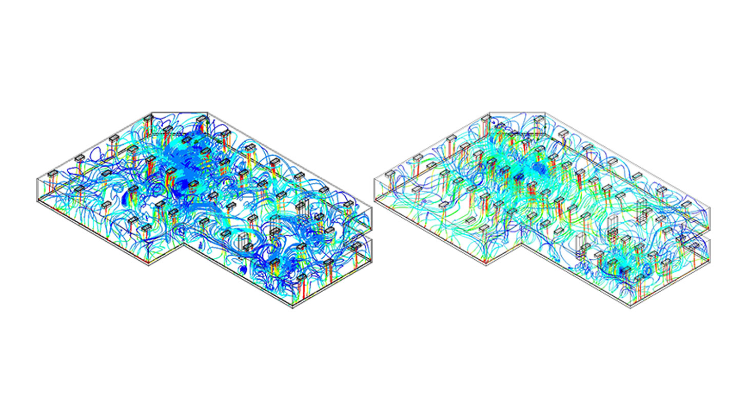
CFD Airflow Modelling is used to demonstrate that air-flow patterns do not present a contamination risk. Cleanroom materials, leakage rates, oxygen requirements, exhaust volume and speed as well as air inflow are calculated and balanced to ensure exact requirements are delivered
The example here shows the calculations and modelling to determine the quantity of fan filter units (FFU) required in a GMP facility: 45 FFUs against 60 FFUs.

Start a project with us
Our design and build specialists have experience working with customers in all kinds of industries on a global scale, achieving great results time and time again. We’d love to work with you as well!

